|
THE TOOLS |
||||||
|
|
BATTERY PLACEMENT MODIFICATION |
|
for Associated TC3 |
These were not my mods, but ones that were found on the web.
| This is how I made the
modifications to my TC3. You will find many pictures of the different
steps of the mod and the tools I used. This idea is not mine, don't ask me
who's original idea this is because I don't know. I read about it on
numerous R/C forum and decided to do it to my car. I just wanted to show
exactly how I did it since I didn't find any "How to's" on the web.
Why do it? I asked myself the same question the first time I read about this mod. Just think about the receivers and ESC's getting smaller and lighter and the 3300 batteries being about 40 grams heavier than the 3000 batts. This results in a very unbalanced TC3. I put my "ready to run" TC3 with a fake transponder (servo's side) and compared the weight of the left and right sides of the car on a Pelouse electronic scale. There was a difference of more than 60 grams, the heaviest being the battery's side (Sanyo 3000). After the mod, the difference was less than 2 grams. So I think the mod is worth it, with the right tools, it should take about two hours of your time. Safety! PROTECT YOUR EYES, WEAR A DUST MASK and take your time. |
|
After viewing a supersized image, use your browser's "BACK" button to get back here. |
|
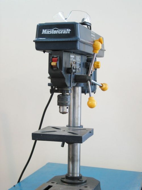
THE TOOLS |
||||||
|
| I put a Dremel high speed cutter #115 in the drillpress' chuck and installed a piece of scrap wood on the table to act as a fence on which the chassis stops so the bit removes 7/64 inch (5.5 mm) from the center of the chassis (fig. 3). I ajusted the down movement so the bit stops just before touching the floor of the chassis and the speed of the motor to 1100 RPM. I started at one end, pushing the chassis against the fence and plunging the bit slowly, moved the chassis and plunged again repeating this until I got to the other side. (fig. 4). | ||||
|
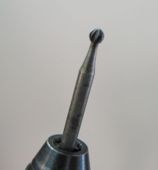
| If you want to have the choice of placing the battery pack towards the front or back of the chassis, you have to take out a little material with a rotary tool to make room for the cell of the battery to fit in its slot (fig. 5). I used the bit shown on my Dremel (fig. 6) and removed a little material at a time, checking with a battery cell for fit, removed a little more, checked for fit until I was satisfied (fig. 7 and 8). | ||||||||
|
| I used the blade of a metal saw to elongate the battery slots (fig. 9), and used a sharp exacto knife to scoar between the cuts, underneath the chassis (fig. 10). I used a small pair of pliers to snap off the pieces (fig. 11). | ||||||
|
| Using a rectangular needle nose file, I smoothed out the edges (fig. 12) and beveled the slots so the cells sit low in the chassis (fig. 13) | ||||
|
| The last thing I did before reassembling the car was to put strips of high density foam to keep the battery pack from moving side to side (fig. 14). | ||
|
|
Here is some other stuff I did to the chassis. To be able to secure the battery pack with either tape or a strap (fig. 15). I made a jig with pieces of scrap wood so the chassis could move from side to side in a straight line, secured the jig to the drillpress' table with C clamps and milled some slots between the cell openings (fig.16) with the Dremel high speed cutter #115. To give more cooling to the motor, I enlarged the hole in the chassis (fig. 17) with the same bit. Again using the same bit, this time in my Dremel rotary tool, I took off some material to make room for the steering turnbuckles (fig. 18) for the NTC3 steering rack conversion. Using a Unibit (fig. 19) I made four holes, two in front and two in back, underneath the diffs, to lighten the chassis a bit more (fig. 20). |
||||||||||||
|
|
AFTER EVERYTHING IS PUT BACK TOGETHER. |
|||
|
|||
|
|
Back to TC3 page |